What is the meaning of CAN Bus?
If you’ve ever wondered about the meaning of CAN bus, it’s best thought of as the nervous system of modern machines – a simple but robust communication network that lets electronic control units share information instantly.
Modern vehicles, machines, and industrial systems contain dozens – sometimes hundreds – of small computers called Electronic Control Units (ECUs). Each ECU manages a specific function: from controlling your car’s brakes and airbags to regulating a robot arm on a factory floor. But with so many devices, how do they all communicate efficiently?
The answer is the CAN bus system – short for Controller Area Network bus.
Originally designed for the automotive industry in the 1980s, CAN bus has since become one of the most widely used communication standards across multiple industries, thanks to its robustness, simplicity, and cost-effectiveness.
At Control Technologies, we help organisations design, implement, and maintain CAN bus systems. We also provide the essential hardware and software tools that engineers need:
- CAN bus interfaces & adapters
- CAN bus analysis software
- Data loggers & analyzers
- Automation solutions
- Digitalisation platforms
This guide will take you through everything you need to know about CAN bus: what it is, how it works, its history, benefits, variants, and how to log and analyze CAN bus data.
P.S. If you’re looking for a more detailed guide about how to implement CAN-Bus in your next machine build, download our guide: “A Machine Builder’s Guide to CAN-Bus“
What Does CAN Bus Stand For?
The term CAN bus can be broken down into:
- CAN (Controller Area Network) → the communication protocol itself.
- Bus → the shared two-wire communication pathway that links devices together.
In other words, the meaning of CAN Bus is simply “a Controller Area Network that allows electronic devices to communicate efficiently over a shared two-wire system.”
Instead of running separate wiring between every ECU, CAN bus allows multiple devices to share one network.
In simple terms: CAN bus protocol is like a group chat for machines. Each ECU can broadcast messages to all others at once, with built-in rules to ensure important messages are heard first.
A short history of CAN Bus
The development of CAN bus is a story of necessity.
- 1983: Bosch began working on a system to reduce complex vehicle wiring harnesses.

- 1986: CAN was introduced at the SAE (Society of Automotive Engineers) conference in Detroit.
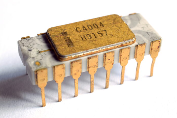
- 1987: Intel and Philips released the first CAN controller chips.
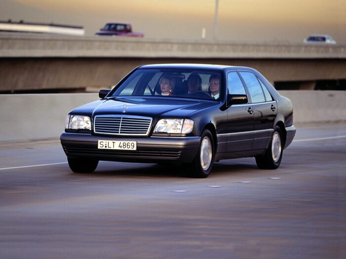
- 1991: The Mercedes-Benz W140 S-Class became the first production car with a CAN bus system.
Since then, adoption has been explosive. Today, CAN bus is standard in:
- All modern passenger cars and trucks
- Heavy machinery and off-highway vehicles
- Industrial automation and robotics
- Aerospace and marine navigation systems
- Medical devices and prosthetics
- Smart infrastructure and building systems
It’s one of the most successful communication protocols ever created.
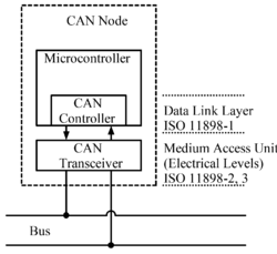
How Does CAN Bus Work?
The Electrical Layer
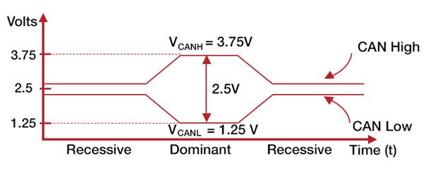
A CAN bus system uses just two twisted wires:
- CAN High (CAN_H)
- CAN Low (CAN_L)
These wires transmit differential signals. Instead of sending a single voltage level (which is vulnerable to noise), CAN transmits two opposite signals and compares them. This makes the system extremely robust in electrically noisy environments like vehicles and factories.
Message-Based Communication
Unlike protocols that address devices directly, CAN bus protocol is message-based.
- Each message is called a frame.
- Frames are identified by an arbitration ID (11 or 29 bits).
- The ID indicates both the type of data and its priority.
Every device (ECU) on the network receives every frame, but each ECU only processes the messages relevant to it.
Arbitration: Resolving Conflicts
Because any ECU can transmit when the bus is free, there needs to be a way to prevent “collisions.” CAN solves this with bitwise arbitration:
- The message with the lowest numerical ID wins priority.
- Other nodes automatically back off and wait.
This ensures that critical signals (like braking) always get through first.
Error Detection & Fault Tolerance
CAN includes multiple layers of error checking:
- CRC checks (Cyclic Redundancy Check)
- ACK bits to confirm receipt
- Error frames to signal corruption
- Automatic retransmission
If a device repeatedly causes errors, it is automatically placed in a bus-off state to protect the rest of the network.
CAN Bus Frame Structure
A CAN frame is the smallest unit of communication.
There are four types of frames:
- Data Frame – Carries actual information.
- Remote Frame – Requests information from another node.
- Error Frame – Signals a problem.
- Overload Frame – Introduces a delay when needed.

A typical data frame includes:
- Start of Frame
- Identifier (ID) – message priority and type
- Control bits
- Data field – up to 8 bytes (Classic CAN) or 64 bytes (CAN FD)
- CRC field
- ACK field
- End of Frame
Benefits of CAN Bus
- Reduced Wiring Complexity
Instead of hundreds of separate wires, CAN bus uses just two — saving weight and cost. - Robust and Reliable
Differential signaling and error handling make it highly resistant to noise. - Prioritisation of Messages
Critical messages always win arbitration. - Scalability
Easily add or remove ECUs without redesigning the network. - Cost-Efficiency
Simpler wiring, fewer components, and standardisation reduce costs. - Wide Adoption & Longevity
Supported across multiple industries and guaranteed long-term availability.
Variants of CAN Bus
Classical CAN (CAN 2.0A/B)
- Introduced in the 1980s
- Supports up to 1 Mbit/s
- 11-bit (2.0A) or 29-bit (2.0B) identifiers
- 8-byte data payload
👉 Buy the PEAK P-CAN USB from the Control Tech UK Webshop

CAN FD (Flexible Data-Rate)
- Introduced in 2012
- Up to 64-byte data payload
- Allows switching to higher bitrates during transmission
- Backward-compatible with Classical CAN
👉 Buy the PEAK P-CAN USB FD from the Control Tech UK Webshop

CAN XL
- Still emerging
- Supports up to 20 Mbit/s
- Payloads up to 2,048 bytes
- Designed for next-generation vehicles, automation, and IoT
CAN Bus Variants, Comparison Table:
| Variant | Max Speed | Max Payload | Use Cases |
| Classical CAN | 1 Mbit/s | 8 bytes | Automotive, industrial, legacy |
| CAN FD | 5–8 Mbit/s | 64 bytes | Modern automotive, robotics |
| CAN XL | 20 Mbit/s | 2048 bytes | Autonomous driving, IIoT, AI |
Applications of CAN Bus Protocol
Automotive
- Engine management
- Transmission control
- ABS and stability systems
- Airbags and safety systems
- EV battery management
- Infotainment

Industrial Automation
- PLCs and robotic systems
- Motor control and drives
- Factory monitoring systems

Medical
- Prosthetics
- Scanners and imaging
- Life-support devices
Aerospace & Marine
- Navigation systems
- Flight control
- Marine engine monitoring

Smart Infrastructure
- Elevators and lifts
- Building management
- Energy optimisation

👉 Explore our automation solutions and digitalisation tools to see how CAN bus can be integrated into your industry.
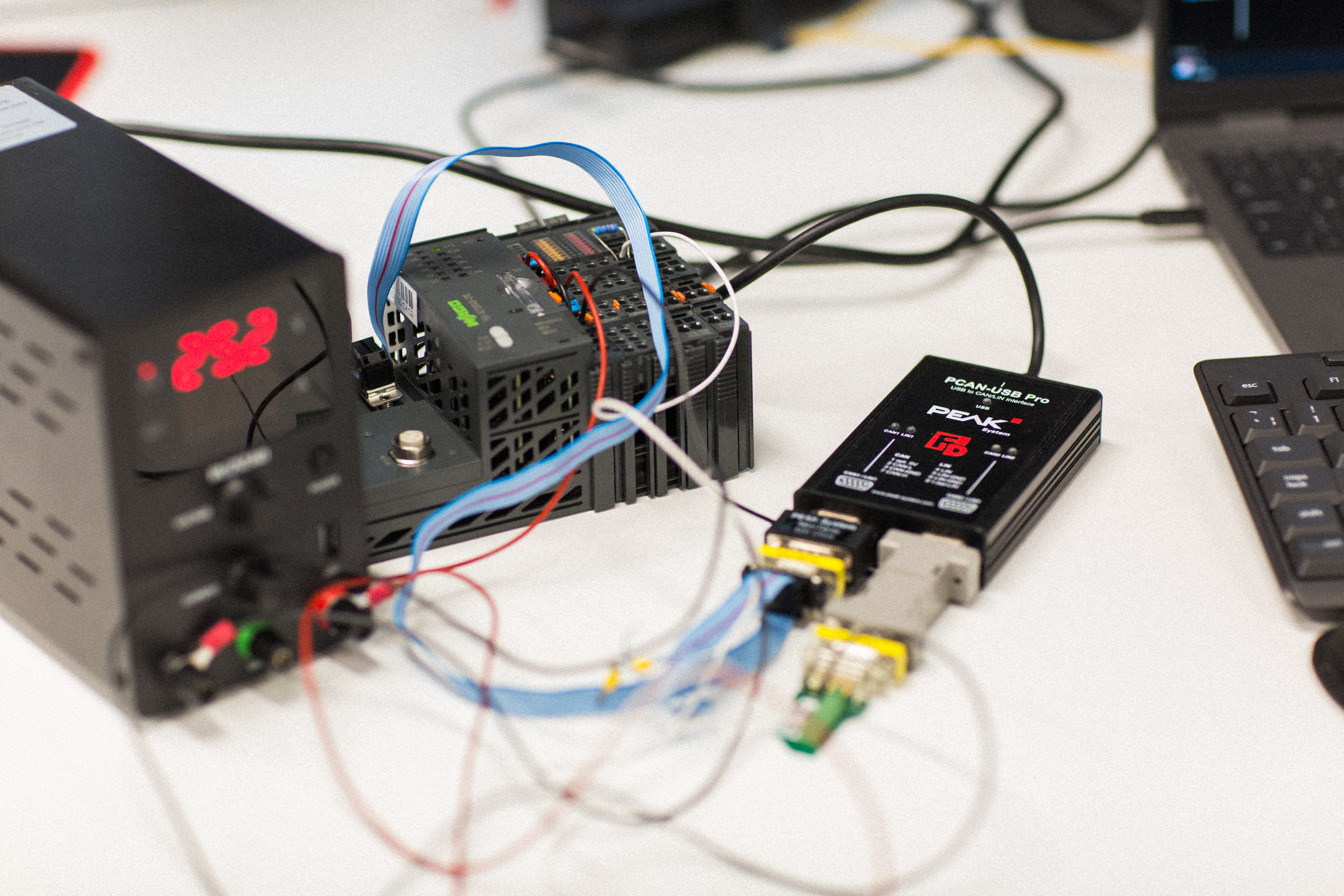
How to Log CAN Bus Data
Logging CAN bus data is essential for diagnostics, R&D, and compliance.
Steps:
- Connect a CAN bus interface to your PC or logger.
- Capture raw CAN frames.
- Decode signals using CAN bus software.
- Analyze data for faults, performance, or predictive insights.
👉 View our range of CAN-Bus loggers at the Control Tech UK Webshop
Why log data?
- Debugging network errors
- Reverse-engineering signals
- Validating ECU designs
- Feeding machine learning systems
- Right-to-repair compliance
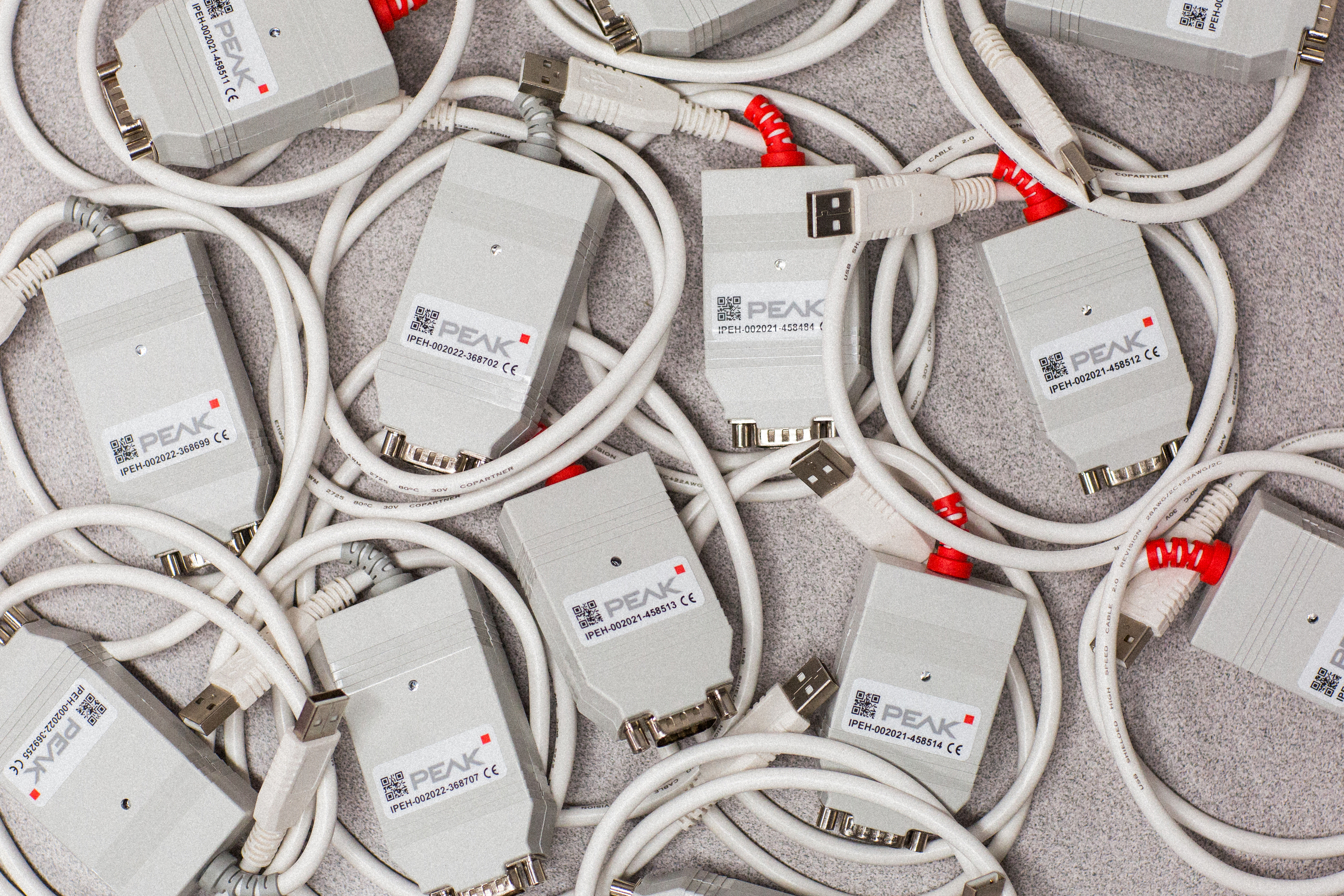
CAN Bus Adapters, Analyzers & Loggers
- CAN Adapters: Connect a PC to the network.
- CAN Loggers: Standalone devices for recording data in the field.
- CAN Analyzers: Software + hardware tools for decoding and troubleshooting.
👉 Explore Control Tech UK’s ranges of CAN tools:
The Future of CAN Bus

Despite being over 40 years old, CAN bus is far from obsolete. Its future lies in:
- CAN FD & XL adoption for autonomous driving and Industry 4.0.
- Integration with Ethernet in hybrid vehicle and factory systems.
- Cybersecurity to protect increasingly connected networks.
- IoT & digitalisation applications beyond vehicles.
- Energy efficiency for low-power devices.
- Rights-to-repair and broader diagnostic access.
👉 Learn how CAN bus fits into Industry 4.0 in our digitalisation solutions.
Engineering Services from Control Technologies
At Control Technologies, we don’t just supply products — we deliver end-to-end CAN bus solutions.
- System design & consultancy
- Hardware integration (interfaces, loggers, analyzers)
- Custom software stacks & diagnostics
- Automation & digitalisation projects
Whether you’re working on a next-generation EV, an industrial automation project, or predictive maintenance in factories, we can help.
Frequently Asked Questions
What is CAN bus?
A robust communication system that allows devices (ECUs) to share data over two wires.
What is the CAN bus meaning?
The CAN bus meaning is straightforward: it stands for “Controller Area Network bus,” a system that allows electronic devices (ECUs) to communicate over a shared two-wire network.
How does CAN bus work?
It uses differential signaling, message identifiers, and arbitration to ensure reliable communication.
What are the benefits of CAN bus?
Reduced wiring, cost savings, robustness, scalability, and wide adoption.
What are the variants of CAN bus?
Classical CAN, CAN FD, and CAN XL.
How do you log CAN bus data?
Using CAN bus adapters, data loggers, and analysis software.
What is the future of CAN bus?
Faster variants (CAN FD, CAN XL), hybrid architectures with Ethernet, IoT integration, and cybersecurity.
Conclusion
The CAN bus system is one of the most successful communication standards in history. From its beginnings in the automotive world, it has expanded to industrial automation, medical devices, aerospace, and beyond.
At Control Technologies, we combine engineering expertise with a full range of CAN bus hardware, software, and data loggers to help organisations harness the power of CAN bus today — and prepare for the future.